HOWTO: Deploy a VMware NSX-V Distributed Logical Router (DLR)
VMware NSX-V VCAP6-NV VCIX6-NV HOWTO
Published on 31 July 2017 by Christopher Lewis. Words: 387. Reading Time: 2 mins.
Introduction
This is one of many posts that will form part of the VCAP6-NV Deploy Exam Guide . In this post, we will cover how to deploy a VMware NSX-V Distributed Logical Router (DLR).
What is a Distributed Logical Router (DLR)?
A Distributed Logical Router (or Logical Distributed Router) is typically used to route East/West traffic between Logical Switches.
In this example, we will create a new DLR with two Internal interfaces to connect the App_Tier and Data_Tier Logical Switches. Finally we’ll add an Uplink interface to connect the DLR to a “transit” logical switch.
Step By Step Guide
Prerequisites
Adding a DLR has a certain amount of prerequisites that can be found within the VMware Doc site here .
Deploying a VMware NSX Distributed Logical Router (DLR)
- Using your favourite web browser, navigate to the vCenter Server login page (
https://vcenter.fqdn).
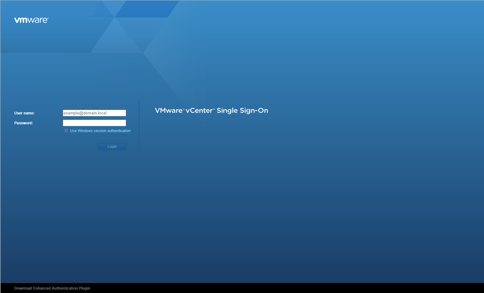
- Type the administrator User name and Password and click Login.
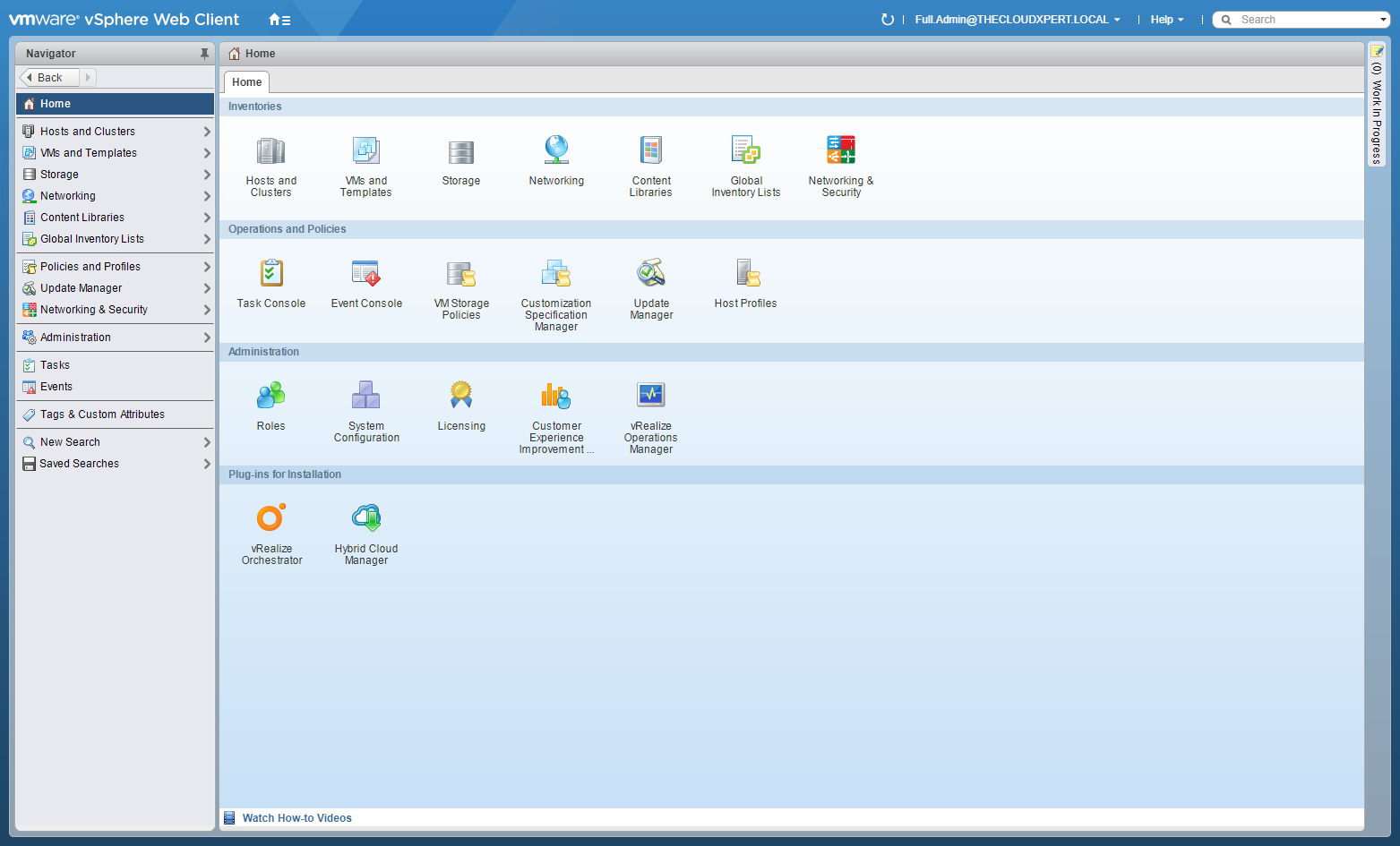
- Click Network and Security.
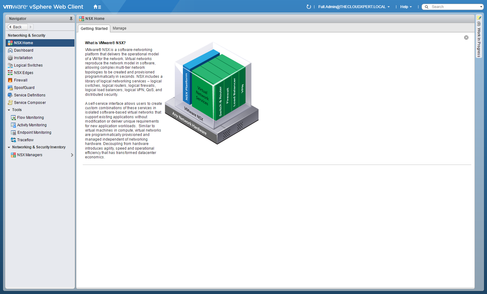
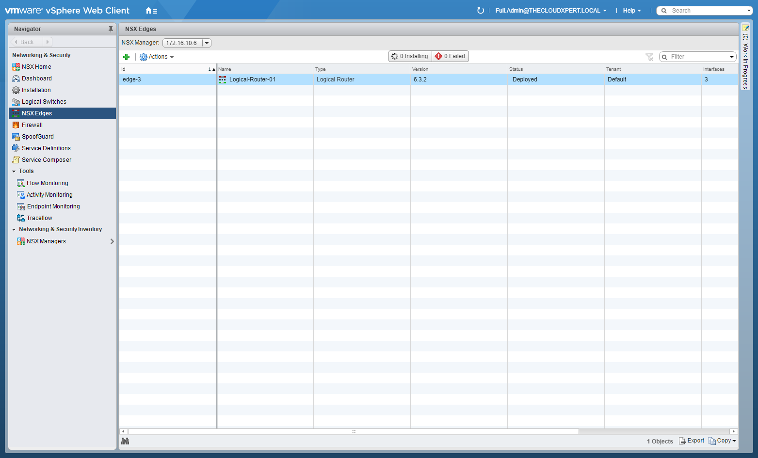
- Click NSX Edges.
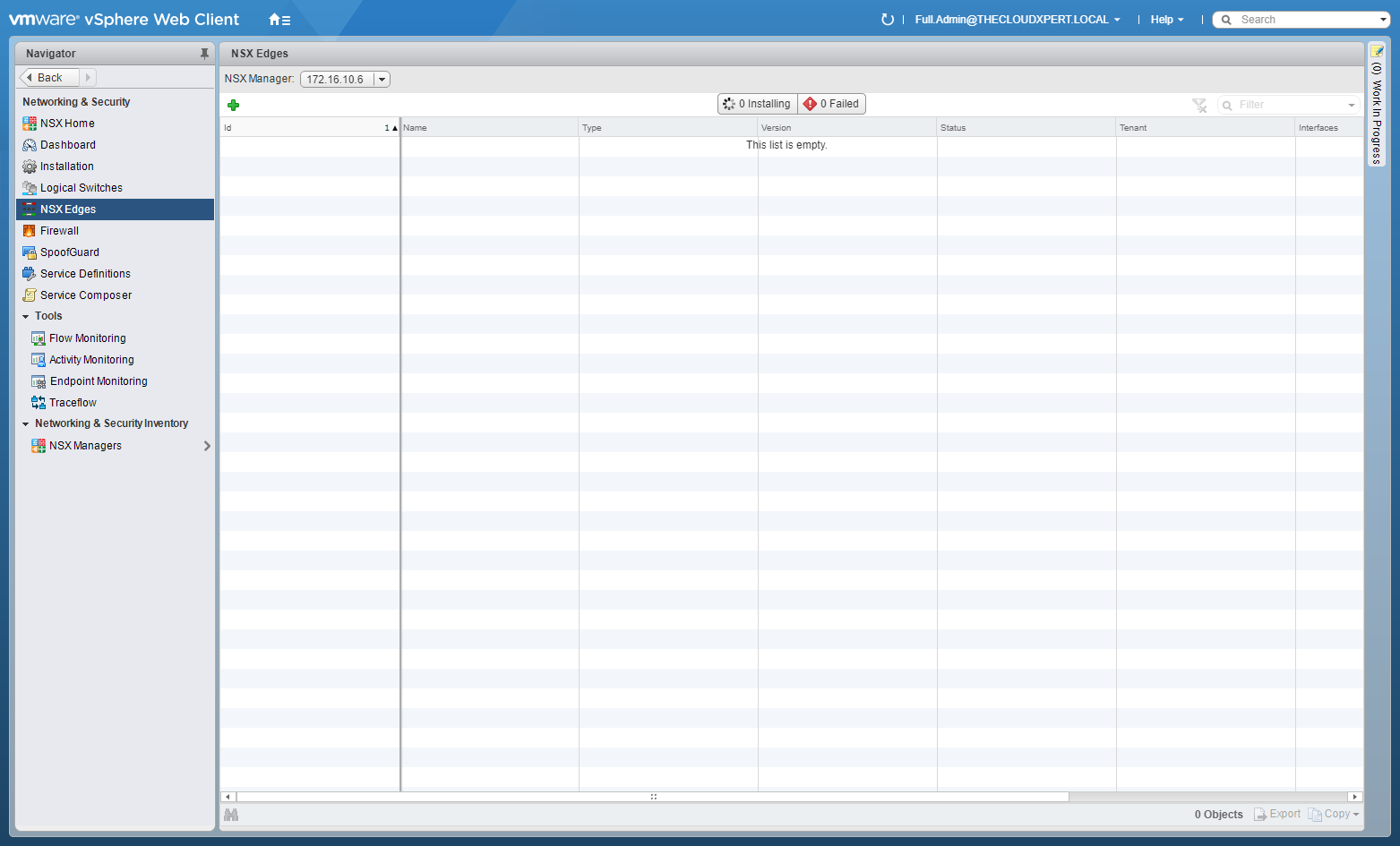
- Click Add (+).
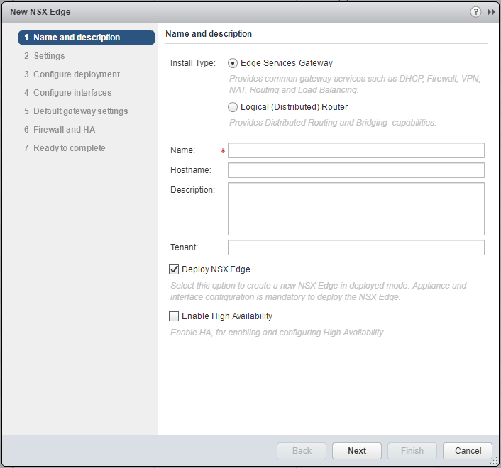
- Select the Logical (Distributed) Router option.
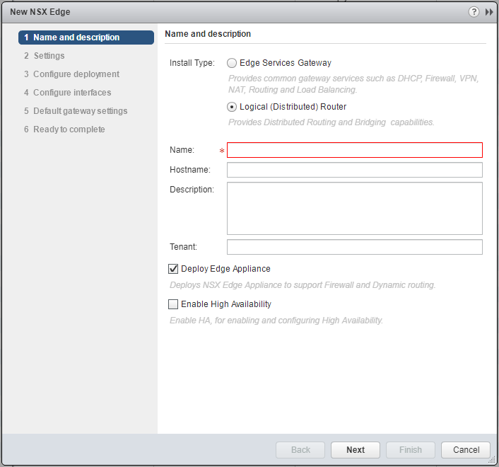
- Type the Name of the new Logical Router, (optionally) type a Hostname, Description and Tenant. (Optionally) choose whether to check/uncheck the Deploy Edge Appliance and Enable High Availability checkboxes.
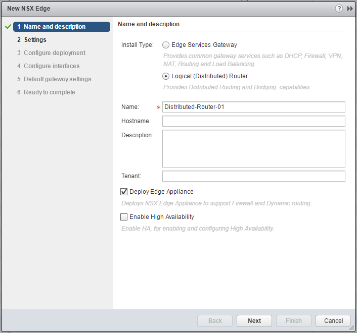
- Click Next.
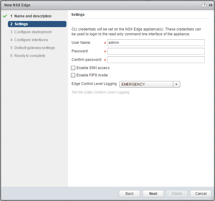
- Type and confirm a Password for the CLI credentials. (Optional) check the Enable SSH access or Enable FIPS mode checkboxes based on your requirements.
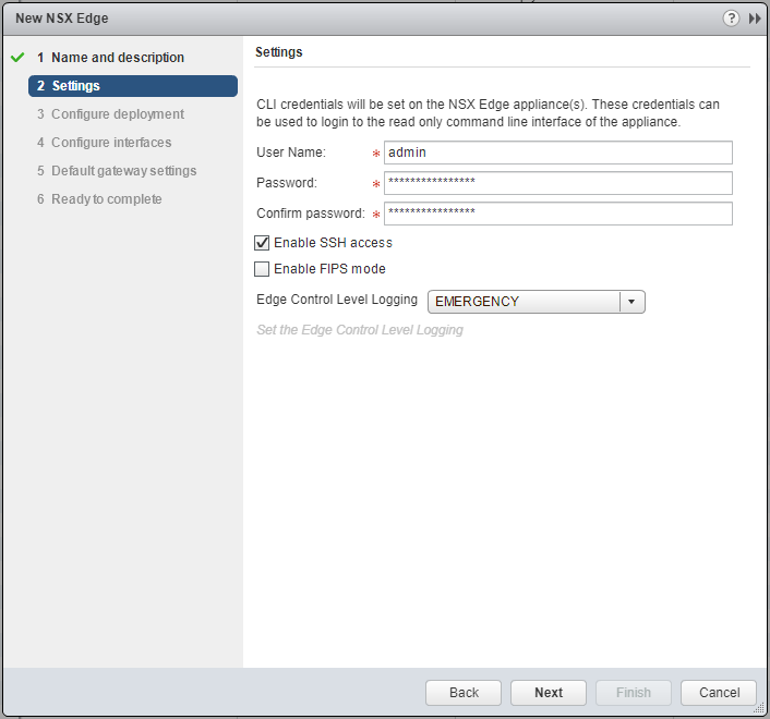
- Click Next.
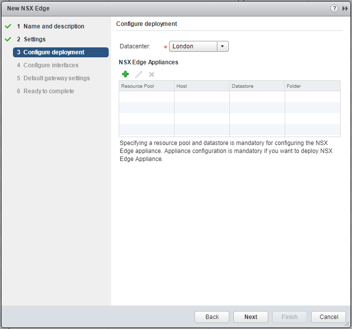
- Click Add (+).
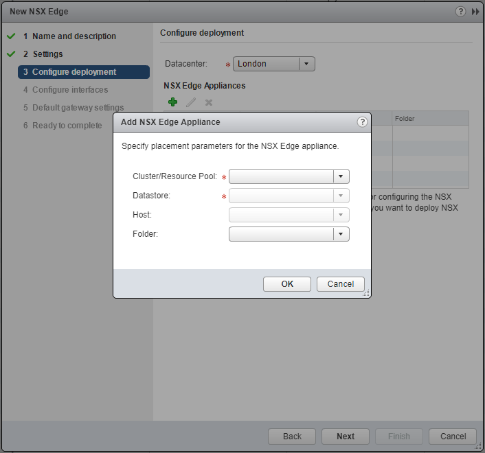
- Select the appropriate Cluster/Resource Pool from the dropdown.
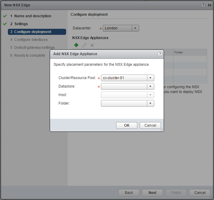
- Select the appropriate Datastore from the dropdown.
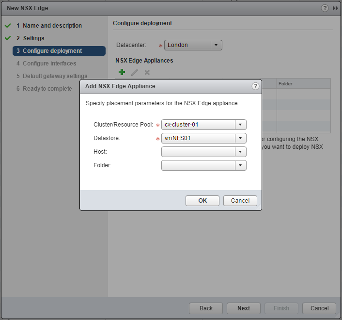
- Click OK.
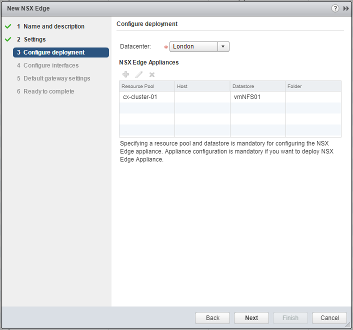
- Click Next.
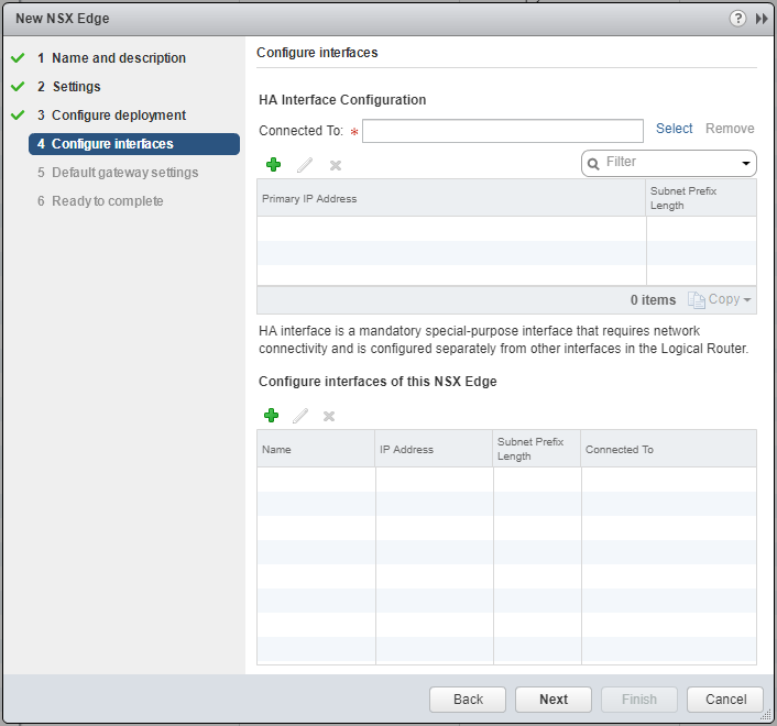
- At HA Interface Configuration, click Select.
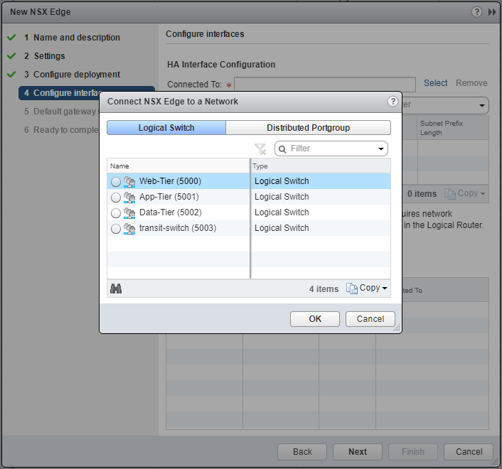
- Select the appropriate network and click OK.
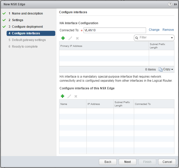
- At HA Interface Configuration, click Add(+).
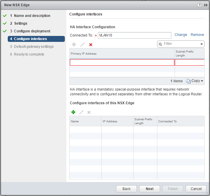
- Type the Primary IP Address and Subnet Prefix Length and click anywhere the window.
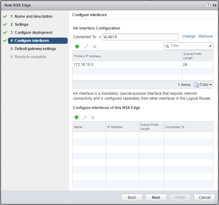
- Under Configure interfaces of this NSX Edge, click Add(+).
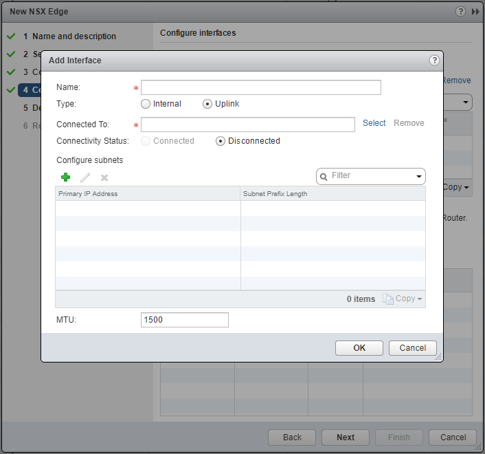
- Type the Name of the interface, and select either the Internal or Uplink option.
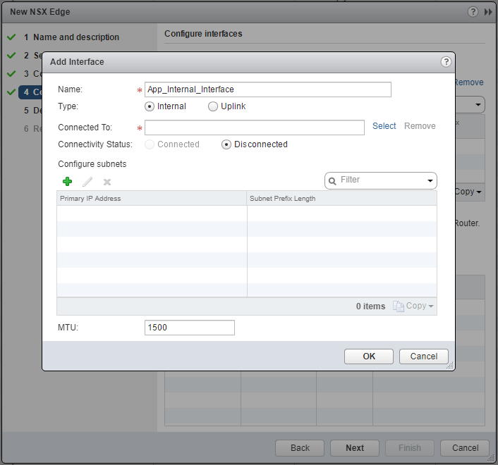
- At Connected To click Select.
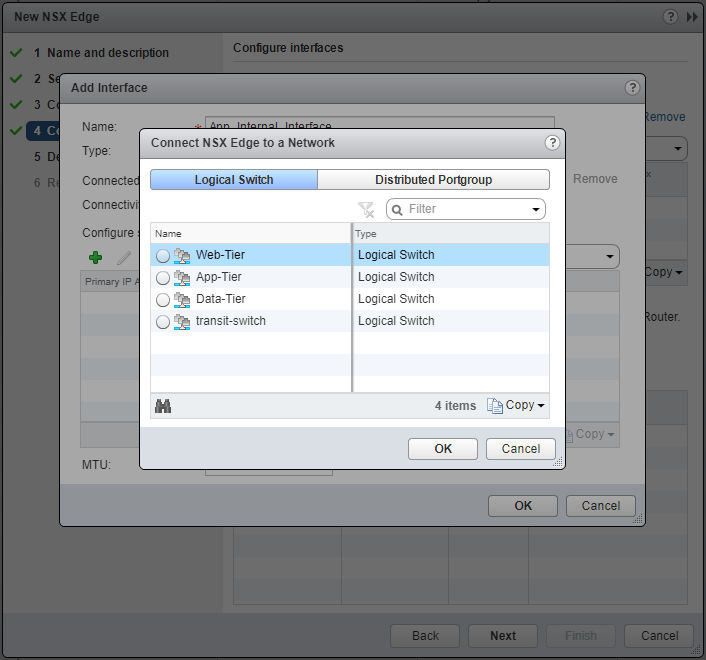
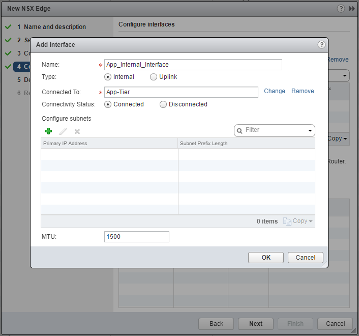
- Select the appropriate Logical Switch and click OK.
- At Configure subnets, click Add(+) and then add the Primary IP Address and Subnet Prefix Length.
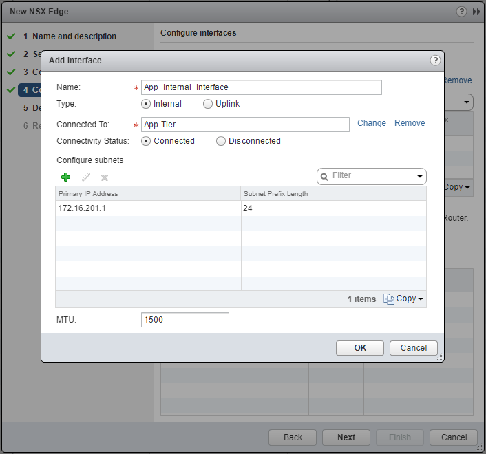
- Click OK.
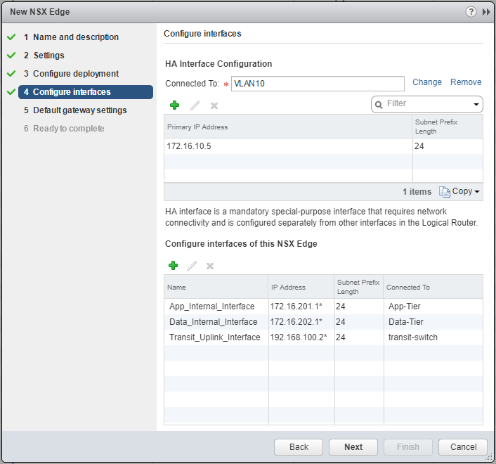
- Click Next.
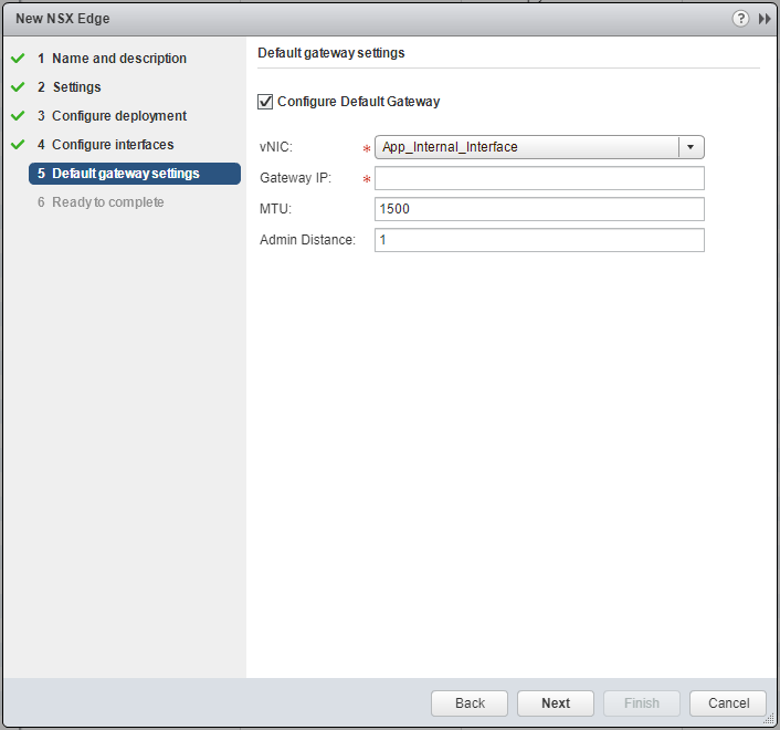
- Select the appropriate interface from the vNIC dropdown and enter the Gateway IP address.
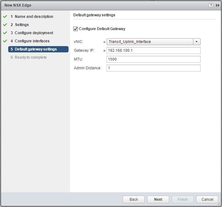
- Click Next.
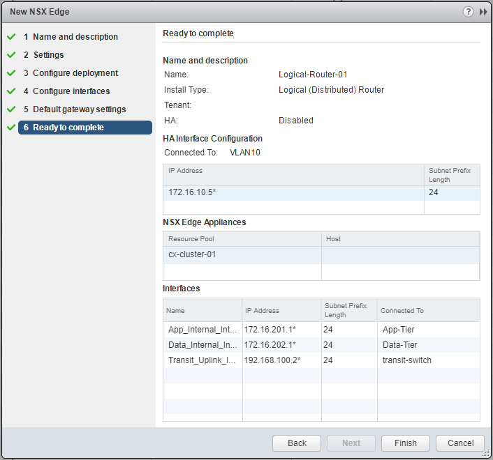
- Click Finish.
Published on 31 July 2017 by Christopher Lewis. Words: 387. Reading Time: 2 mins.
- VCAP6-NV Deploy - Objective 1.1 - Deploy VMware NSX Infrastructure components ()
- HOWTO: Add a Host to a VMware NSX-V enabled vSphere Cluster ()
- HOWTO: Remove a Host from a VMware NSX-V enabled vSphere Cluster ()
- HOWTO: Exclude Virtual Machines from Firewall Protection in NSX-V ()
- HOWTO: Deploy the VMware NSX-V Controller(s) ()

